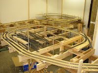
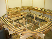
 Next step is to layout the helix. We wanted a slow and easy grade in the dual track helix. The plan had a 36"x48" area for the helix and we were planning on a 4" altitude change per loop. This would give us enough clearance between each loop to not scrape the roof of any car we were planning on running with the gentlest grade without greatly increasing the size. Linear feet per loop was ~12' (144") with a 4" rise or 2.7% grade (4/144).
 This helped set the upper level as 3 loops gave us 12" of difference (was in our initial plan but wanted to make sure prior to literally nailing anything down). We added the upper level supports then started creating the Helix loops. This is where the L part really came in useful. So much so we added Ls to some of the lower level supports to aid in helix creation. What we did is to layout the area the helix would run with cardboard making sure clearance track to track was sufficient to the longest of cars would not collide if we had trains meet in the loop.
 This provided templates for the custom cut straights and curve pieces of plywood for the dual loop. We cut the pieces wide enough for the vertical supports to run through them. The supports we chose were 1/4" x 20 threaded rod. Reasons were low priced, and very flexible as all we had to do to tweak the rise was to move a couple nuts, plus one set of rods would run through all levels of the helix making it quite a compact setup. Remember to verify the cars will not hit the rods when running the loops.
As you can see in the pictures we ran the threaded rod through the L and nutted it down. Of course we used washers to avoid the nuts cutting through the wood. so from bottom up the rod was nut, washer, L, washer, nut, space, nut, washer, plywood, washer, nut, etc.
The upper pic you can see the start for both helix loops and the lower level track feed. These are Gilder in the foreground and Floren in the back (I think the plans were written before final names assigned). The middle pic is Gilder where the mining area will be to the left of what you see. The lower pi is 3 loops of the Floren helix. You can see the upper level supports and the background board in plase, but that is another posting.
No comments:
Post a Comment