There is a bunch to do here.
1. Making a pine tree - I used the wire, rope, and straw method (as in a different post here).
2. making a landscape with a foam base and plaster over the top and formed to the final shape.
3. Making believable snow on the trees, in drifts, and on the ground
4. making ice to look real.
5. sidewalk options (mainly for coloration purposes)
So first thing is the foundation - I did a little shaping of the foam, but not too much. Mainly getting a slight depression for the iced over pond. Once that was ready I covered the foam with plaster of paris. much more shaping now, this was quite dusty so if you can do this not in an enclosed area I would suggest it.
After getting the pond the way I like, I added a sidewalk flat run using a popsicle stick. Next step is to work on the pond. First try was pearl white glass glazing. Issue I had was it was not thin enough to flatten out. Magic water was super in flattening out but was clear (unrealistic for anyone in the northern climes can testify to). Coat 3 I mixed the glazing into the magic water. This was acceptable, but I will work on it more prior to implementing in my layout.
Next was the snow. I got the snow bottle (very small white glass beads) from the local model store. I do recommend a breathing mask for these as it would be pretty easy to inhale these beads. At the local big box store I got a small can of thicker white latex primer. I covered the snow areas with the latex and sprinkled the paint with the snow beads. This added a nice sparkle that snow has.
Next step was to setup the sidewalks. I decided to go with a dark walk as to add contrast to the all white of the snow. I used patching concrete that feathers out to a thin layer. I slowly applied the thinned concrete being careful to not get into the snow.
Next I set in the 2 trees I made bracketing the pond. Long term if I was doing this on a layout I would also be setting in limp poles to light the walk for evening strolls.
I took the white primer and mixed the beads in 50/50 (what I got from research). This made a nice paste type fluid that was just thick enough to mold a little without forming sharp peaks. I smoothed out several drifts and proceeded to drip the snow on the trees to get the snowed on look. In the future I think I would start with a thinner mix for the trees and move my way up to the 50/50.
Finally I added some people and took the pic. Not fully happy with the results, but this gives me enough information to help when I do this on the layout.
Tuesday, March 20, 2012
Sunday, March 18, 2012
Creating out of cheap stuff - The chain link fence
In doing research I saw a bit of information I wanted to try. A how to make a good looking chain link fence.
I got 1/16" polystyrene rods (I know not scale but anything smaller would be real tough to work with first go) for the fence posts and rails. I went down to the local river area and gathered small rounded rocks of varying sizes 1/4" to 1/2" and I made a run down to the local Michaels to buy a childs wedding veil and a can of aluminum colored spray paint.
I already had a hardwood tree made and the needed ground cover for a small grass hill.
I first grabbed a block of Styrofoam for the test, about a 6"x6" was super. I wanted to have a hill and a reason for the fence so I wanted to have a rock retaining wall with either a future creek, road, or rail line would run.
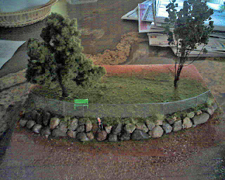 I mixed the plaster up and created a mound with a sharp drop off of about 1" to the front.
Once set I drilled holes the size of the pipes about 8' in scale apart. I cut off the vertical posts and smoothed the cut ends putting in a slight depression to help hold the horizontal pole. They were glued into the holes to be about 1" above the plaster. I slowly glued the horizontal pole in place one post at a time.
Once set it was time to paint the poles and initial brown of the ground.
Next step I did was the retaining wall. I slowly stacked rocks until I got the look and feel I was looking for. Once all was in place white glue (full strength) was poured behind the rocks a little at a time until the whole wall was secure. Another glue would have probably worked better but it was late and I was not looking to go shopping.
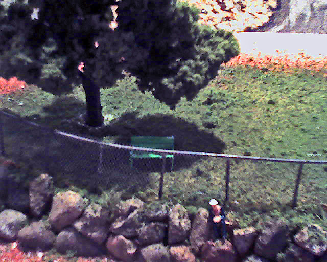 I followed standard grass laying techniques with the color and styles of green ground foam. I then cut a strip of wedding veil just slightly wider than the fence was tall. Just a little as I would match it up at the top and could add taller grass/bushes at the bottom if the fence did not make it all the way down.
I did a quick spray of the aluminum color to the veil and attached after the paint was quite dry. Standard styrene glue worked super for this as it did for the rails.
I added a few touches and shot the pics - Couple trees, park bench, and man sitting on the wall. I added some taller shoots of grass in the rocks and a couple weeds. For a real layout I would work more on the appearance of the wall by finding one similar and shoot some pics to compare to.
If you look closely at the above pic you can see the fence and it looks fairly real. Not to bad for a quick evening slam it together to see how ti looks thing.
FYI - I took the shots on my kitchen island. The overhead lights actually added a nice touch of what looks like the suns shadow under the tree. Sometimes it is better to be lucky than good......
I got 1/16" polystyrene rods (I know not scale but anything smaller would be real tough to work with first go) for the fence posts and rails. I went down to the local river area and gathered small rounded rocks of varying sizes 1/4" to 1/2" and I made a run down to the local Michaels to buy a childs wedding veil and a can of aluminum colored spray paint.
I already had a hardwood tree made and the needed ground cover for a small grass hill.
I first grabbed a block of Styrofoam for the test, about a 6"x6" was super. I wanted to have a hill and a reason for the fence so I wanted to have a rock retaining wall with either a future creek, road, or rail line would run.
 I mixed the plaster up and created a mound with a sharp drop off of about 1" to the front.
Once set I drilled holes the size of the pipes about 8' in scale apart. I cut off the vertical posts and smoothed the cut ends putting in a slight depression to help hold the horizontal pole. They were glued into the holes to be about 1" above the plaster. I slowly glued the horizontal pole in place one post at a time.
Once set it was time to paint the poles and initial brown of the ground.
Next step I did was the retaining wall. I slowly stacked rocks until I got the look and feel I was looking for. Once all was in place white glue (full strength) was poured behind the rocks a little at a time until the whole wall was secure. Another glue would have probably worked better but it was late and I was not looking to go shopping.
 I followed standard grass laying techniques with the color and styles of green ground foam. I then cut a strip of wedding veil just slightly wider than the fence was tall. Just a little as I would match it up at the top and could add taller grass/bushes at the bottom if the fence did not make it all the way down.
I did a quick spray of the aluminum color to the veil and attached after the paint was quite dry. Standard styrene glue worked super for this as it did for the rails.
I added a few touches and shot the pics - Couple trees, park bench, and man sitting on the wall. I added some taller shoots of grass in the rocks and a couple weeds. For a real layout I would work more on the appearance of the wall by finding one similar and shoot some pics to compare to.
If you look closely at the above pic you can see the fence and it looks fairly real. Not to bad for a quick evening slam it together to see how ti looks thing.
FYI - I took the shots on my kitchen island. The overhead lights actually added a nice touch of what looks like the suns shadow under the tree. Sometimes it is better to be lucky than good......
Tuesday, March 13, 2012
Benchworks basics - Rail line foundations
Now that we had the basic supports for the landscaping in place and a rough draft of location of the loops we can start putting down the foundation to lay the rail onto.
 We started with the standard 1/4" plywood cut in strips about 4" wide. We attached these to the supports giving a reasonable bed to build upon. On top of the plywood was laid hemosote cut in strips about the same width. FYI this is old school way that my co-builder grew up with. Since we are now both over 50 that is quite old at that.
 Steve researched a bit and discovered a method that is far more sturdy and has less waste, we all like that. Basically making a 7 layer thick plywood using hardboard. This does take LOTS of wood glue, so a good foam roller will help lots here. Also you will be clamping the strips every few inches so a large bunch of spring clamps will be needed. I will have to explain a bit and I hope the pics will do it justice.
We bought a sheet of 1/8" thick hardboard and cut it into 3/4" wide strips about 4' long. While this made LOTS of dark brown saw dust (which I am looking for a way to use), it made an easy to carry and store stack of material. Basically we set a 1.5"-2" wide T attached to the landscape braces setting the top of the T about 1" under where we wanted the final track height to be. Once a run of these braces were set, looking like a set of bridge trusses without the bridge, we started setting the hard board down. This was done a few strips at a time making sure the strips do not end any where near each other (this adds lots of strength).
Glue up one side of a strip and apply it to the side of another.
A few of the good reasons to go with this type of rail-bed are:
 We started with the standard 1/4" plywood cut in strips about 4" wide. We attached these to the supports giving a reasonable bed to build upon. On top of the plywood was laid hemosote cut in strips about the same width. FYI this is old school way that my co-builder grew up with. Since we are now both over 50 that is quite old at that.
 Steve researched a bit and discovered a method that is far more sturdy and has less waste, we all like that. Basically making a 7 layer thick plywood using hardboard. This does take LOTS of wood glue, so a good foam roller will help lots here. Also you will be clamping the strips every few inches so a large bunch of spring clamps will be needed. I will have to explain a bit and I hope the pics will do it justice.
We bought a sheet of 1/8" thick hardboard and cut it into 3/4" wide strips about 4' long. While this made LOTS of dark brown saw dust (which I am looking for a way to use), it made an easy to carry and store stack of material. Basically we set a 1.5"-2" wide T attached to the landscape braces setting the top of the T about 1" under where we wanted the final track height to be. Once a run of these braces were set, looking like a set of bridge trusses without the bridge, we started setting the hard board down. This was done a few strips at a time making sure the strips do not end any where near each other (this adds lots of strength).
Glue up one side of a strip and apply it to the side of another.
- Solid - When you finish the 5 layer sandwich (for HO scale) this is solid.
- Easy prep for the rail - just need to run a belt sander lightly to even out the top
- easy to build landscape off of - If you like the basket weave cardboard strips this is a real easy rail bed to attach to since there is a nice sized side.
- Even sweeps on curves - due to the way you build the sandwich the curves are quite uniform so you do not have any sudden diameter changes
- complex curves easy - S curves while a bit of work are easier IMHO than other rail beds we have tried
- low scrap - you are not cutting out bends out of plywood and having lots to toss.
A couple drawbacks are:
- You will use LOTS of glue - I do mean LOTS
- this takes more time - you have to let the glue harden and you have to be aware of ending each layer away from the other layers.
- tough to modify/takes much more planning - once laid out it is what it is. not something you can tweak. Hence this is not a track bed you can change on the fly.
More detail to come on this new bed - I am not liking my explanation will ask my co-builder to help on this. Or I will look for articles/pics on how to.
Wednesday, March 7, 2012
Benchwork - Backdrop time
Now the supports are up time to see why we ran the furring strips on the wall to the ceiling....
We wanted to have the view of a sky and distant hills on the wall to add more depth and realism. We discovered 3 ways to do this:
We did not like #1 as the wall was not all that smooth (it is a basement after all) and we did not feel like trying to get a primer of the right texture that would work.
 #3 was an idea we discovered after we choose, basically go to your local big box home improvement store and get some scrap or remnant pieces of linoleum. Color does not matter as you will be placing the "colored" side to the wall leaving the underside out. bends easy and is easy to work with. Dern, to late for us.....
So option 2 was the choice. We cut the hardboard into 3' strips (the space from the top of the landscape level to near the ceiling), and attached to the furring strips with 3/4" wall board screws.
I went to the paint department of the big box store and got a bunch of the blue paint swatches. I brought these and a couple pictures of mountain scenes we liked the colors of (mainly the sky) down to the room and laid them out under the same lights the layout would use. Important to use the same lighting as your vision perception of color changes with type of color. You do not even realize how much until you use a camera without flash and look at the results. Who has not taken a picture of someone under incandescent bulbs that looked good at the time, but you were shocked how yellow the shot became under the neutral eye of a camera.
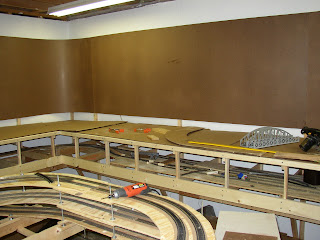
You can see the hardboard bent at a nice radius in the corner (linoleum would have been easier!) but we had to watch it as it wanted to flex to the wall if we were not careful putting it up.
.
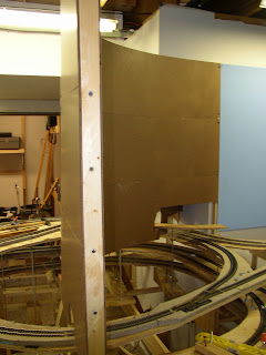
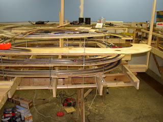
 We decided on that split the helix at the inside corner of the L in the room about 50/50. This gave us the ability to change scenes between sides of the wall and forced a person to have to walk around the entire L to see the rest of the room. Accidentally ended up being a real nice dramatic effect as you walk and keep seeing more.... From that decision we needed a S type bend (as seen in the left pic) and a C shape backed up to it (as seen on the right pic) We ended up using the short strips cut off the other sheets and I cut some braces (1" boards with the curves cut in on both sides) to put between the hard board sheets. Ended up working pretty good.
We picked the color that most closely matched the picture and had a quart mixed. If you look at pics you will notice a couple things about the sky. It is a lighter blue near the horizon and much deeper as you get closer to the zenith. Since we were mainly dealing with sky closer to the horizon we choose the color applicably.
Also on trees you paint in the background the more distant the bluer they are. So choose your near tree color and add little bits of sky blue into the color as you move back.
As you can see above we initially painted the hardboard thinking the seams and screws would not be that visible once painted. We were wrong. They really showed. So we had to treat the screws and seams like we would if this was wallboard. It was spackle time.......
Time to think about horizons and clouds.......
We wanted to have the view of a sky and distant hills on the wall to add more depth and realism. We discovered 3 ways to do this:
- use the existing wallboard
- use hardboard
- use floor linoleum
We did not like #1 as the wall was not all that smooth (it is a basement after all) and we did not feel like trying to get a primer of the right texture that would work.
 #3 was an idea we discovered after we choose, basically go to your local big box home improvement store and get some scrap or remnant pieces of linoleum. Color does not matter as you will be placing the "colored" side to the wall leaving the underside out. bends easy and is easy to work with. Dern, to late for us.....
So option 2 was the choice. We cut the hardboard into 3' strips (the space from the top of the landscape level to near the ceiling), and attached to the furring strips with 3/4" wall board screws.

I went to the paint department of the big box store and got a bunch of the blue paint swatches. I brought these and a couple pictures of mountain scenes we liked the colors of (mainly the sky) down to the room and laid them out under the same lights the layout would use. Important to use the same lighting as your vision perception of color changes with type of color. You do not even realize how much until you use a camera without flash and look at the results. Who has not taken a picture of someone under incandescent bulbs that looked good at the time, but you were shocked how yellow the shot became under the neutral eye of a camera.
You can see the hardboard bent at a nice radius in the corner (linoleum would have been easier!) but we had to watch it as it wanted to flex to the wall if we were not careful putting it up.
.

 We decided on that split the helix at the inside corner of the L in the room about 50/50. This gave us the ability to change scenes between sides of the wall and forced a person to have to walk around the entire L to see the rest of the room. Accidentally ended up being a real nice dramatic effect as you walk and keep seeing more.... From that decision we needed a S type bend (as seen in the left pic) and a C shape backed up to it (as seen on the right pic) We ended up using the short strips cut off the other sheets and I cut some braces (1" boards with the curves cut in on both sides) to put between the hard board sheets. Ended up working pretty good.
We picked the color that most closely matched the picture and had a quart mixed. If you look at pics you will notice a couple things about the sky. It is a lighter blue near the horizon and much deeper as you get closer to the zenith. Since we were mainly dealing with sky closer to the horizon we choose the color applicably.
Also on trees you paint in the background the more distant the bluer they are. So choose your near tree color and add little bits of sky blue into the color as you move back.
As you can see above we initially painted the hardboard thinking the seams and screws would not be that visible once painted. We were wrong. They really showed. So we had to treat the screws and seams like we would if this was wallboard. It was spackle time.......
Time to think about horizons and clouds.......
Monday, March 5, 2012
Benchwork basics - Level 2
OK, so we have the lower rail yards and the elevating helixes in place, time to add the second level bench work and to start layout out the track paths. We will call this the landscape level as the lower level has none.
We started with the bracing to hold up any of the future landscaping. You can see in the picture to the left the braces being installed and tested for correct altitude and levelness.
When designing think in 3d, basically having tracks at different altitudes and changing levels while in view.
We wanted sever levels of traffic in the landscape so after a switch setup we ran the helix one more lap. This got one layer of track 4" higher than the base layer.
In the picture to the right you can see the crisscross of the track at the lower landscape level and the end of the dual track helix another 4" up. this gave us some real interesting twists we can do with the track loops.
Once we had all the initial landscape level bracing in place it was time to lay out the track to see how it would work. We laid out cardboard sheets over the area and started to lay out the track. We used our imagination to see the altitude changes between track lines. Even so we discovered a couple changes in track pathing that would help out what we were trying to accomplish.
We decided which tracks to have exposed, which to put behind the ski mountain (the location we have in the pics, but we did this one section at a time for the entire layout), and where/how to transition between.
Once completed we took overhead shots and I knitted them together to form a panorama from which to work. We also put this down on paper in the form of a plan. This greatly helped us as we started the long process of laying track foundation pieces.
Below is the panorama.
We had fun placing various bridges we had discussing where/how scenarios (one of the dream pieces of the process). The plan you see here has changes several times since as ideas were tossed around after an inspiration or one of us seeing something somewhere that got I wanting it on our layout.
That would be another suggestion I would have, don't be afraid to change something. My first attempt at a trestle bridge is having a major change, but that is another post......
Benchwork basics - To helix or not to helix......
In our design this level was designated train storage and return loop that would be hidden from normal view. Once the lower level supports was complete we laid plywood down for the tracks. we added applicable switches and a dual train yard, one for each main loop. Since this really did not have any real imagination it was an easy job to lay down a one to many to one track layout for each loop. We ended up with 6 track wide train yard for each loop. More than enough for anything we were planning on running.
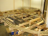 Next step is to layout the helix. We wanted a slow and easy grade in the dual track helix. The plan had a 36"x48" area for the helix and we were planning on a 4" altitude change per loop. This would give us enough clearance between each loop to not scrape the roof of any car we were planning on running with the gentlest grade without greatly increasing the size. Linear feet per loop was ~12' (144") with a 4" rise or 2.7% grade (4/144).
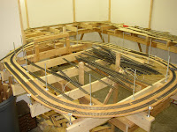 This helped set the upper level as 3 loops gave us 12" of difference (was in our initial plan but wanted to make sure prior to literally nailing anything down). We added the upper level supports then started creating the Helix loops. This is where the L part really came in useful. So much so we added Ls to some of the lower level supports to aid in helix creation. What we did is to layout the area the helix would run with cardboard making sure clearance track to track was sufficient to the longest of cars would not collide if we had trains meet in the loop.
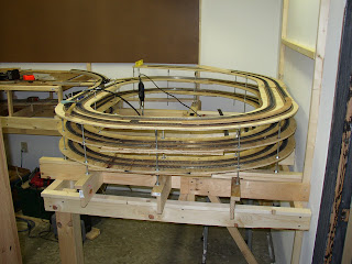 This provided templates for the custom cut straights and curve pieces of plywood for the dual loop. We cut the pieces wide enough for the vertical supports to run through them. The supports we chose were 1/4" x 20 threaded rod. Reasons were low priced, and very flexible as all we had to do to tweak the rise was to move a couple nuts, plus one set of rods would run through all levels of the helix making it quite a compact setup. Remember to verify the cars will not hit the rods when running the loops.
As you can see in the pictures we ran the threaded rod through the L and nutted it down. Of course we used washers to avoid the nuts cutting through the wood. so from bottom up the rod was nut, washer, L, washer, nut, space, nut, washer, plywood, washer, nut, etc.
The upper pic you can see the start for both helix loops and the lower level track feed. These are Gilder in the foreground and Floren in the back (I think the plans were written before final names assigned). The middle pic is Gilder where the mining area will be to the left of what you see. The lower pi is 3 loops of the Floren helix. You can see the upper level supports and the background board in plase, but that is another posting.
 Next step is to layout the helix. We wanted a slow and easy grade in the dual track helix. The plan had a 36"x48" area for the helix and we were planning on a 4" altitude change per loop. This would give us enough clearance between each loop to not scrape the roof of any car we were planning on running with the gentlest grade without greatly increasing the size. Linear feet per loop was ~12' (144") with a 4" rise or 2.7% grade (4/144).
 This helped set the upper level as 3 loops gave us 12" of difference (was in our initial plan but wanted to make sure prior to literally nailing anything down). We added the upper level supports then started creating the Helix loops. This is where the L part really came in useful. So much so we added Ls to some of the lower level supports to aid in helix creation. What we did is to layout the area the helix would run with cardboard making sure clearance track to track was sufficient to the longest of cars would not collide if we had trains meet in the loop.
 This provided templates for the custom cut straights and curve pieces of plywood for the dual loop. We cut the pieces wide enough for the vertical supports to run through them. The supports we chose were 1/4" x 20 threaded rod. Reasons were low priced, and very flexible as all we had to do to tweak the rise was to move a couple nuts, plus one set of rods would run through all levels of the helix making it quite a compact setup. Remember to verify the cars will not hit the rods when running the loops.
As you can see in the pictures we ran the threaded rod through the L and nutted it down. Of course we used washers to avoid the nuts cutting through the wood. so from bottom up the rod was nut, washer, L, washer, nut, space, nut, washer, plywood, washer, nut, etc.
The upper pic you can see the start for both helix loops and the lower level track feed. These are Gilder in the foreground and Floren in the back (I think the plans were written before final names assigned). The middle pic is Gilder where the mining area will be to the left of what you see. The lower pi is 3 loops of the Floren helix. You can see the upper level supports and the background board in plase, but that is another posting.
Sunday, March 4, 2012
Back to basics - Initial benchwork
Thought that I should get back to where we started.
First thing to do when you awant to create a layout is to plan. I would suggest you start with an outline. Items to have on the list incude scale and track code (we chose HO scale and code 100 track), era to model (we chose the 60s) as this will change the scenery and rolling stock you can or should not use. Also to add to the list are items you want to have in the layout (e.g. large city, or mountain).
Additional things to decide prior to hammering the first nail:
We decided on having 2 levels, the lower for a rail yard to stoe trains, and the upper for show.
We stup helixes on each end to lift the trains from level to level. Like everyone olse we will turn these into mountain tops. We are looking at putting 2 cities, a large one in the middle and a smaller one near one end.
There are a bunch of layout pics we looked at that had ideas we liked. So we worked at getting a decent flow as we moved around the layout.
We are both movie buffs with "The Princess Bride" as one of our favorites. So we decided to insert movie pieces into the layout. Fun for us and a task for viewers tofind as many movie references as they can find.
The ends of the lines are Gilder and Floren (countries from the Princess Bride). The main city is Hilldale and the town is Bedford Falls. Thre will be many more movie bits inserted.
L-Girder installation was pretty easy. We had decided in a braced front so there would not be any legs to stub our toes upon. Se started with 1x2 furring strips on the wall then angled brace and top joist we leveled and set a level line down the wall so every one would be at the same altitude. A laser level really helped this process. They are not to expensive or your neighbor might have one you can borrow for a couple hours. We capped each one of these with a 1x2 forming an L or more accurately looks liek a 7 (use for this top horizontal piece will be seen shortly). We added the front "7" and a diagonal support as seen above. The advantage is we would not have any legs needed on the front of the bench work. We took our time making sure everything was level regardless of from where to where we checked. We worked with a standard shelf width of 20" with expansion to 36"x48" for each helix.
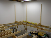
Once the initial front/back braces were set we laid down the 1x4 joists spacing them 24" apart as the default.
Pretty quickly we had what looked like a long wrap around shelf in the making.
I do suggest you read all the posts on bench work prior to starting yours. You might see something in a latter posting that will make you slap you head saying "DOH!" if you don't.
Next post will be finishing the lower bench work and adding the upper level.
First thing to do when you awant to create a layout is to plan. I would suggest you start with an outline. Items to have on the list incude scale and track code (we chose HO scale and code 100 track), era to model (we chose the 60s) as this will change the scenery and rolling stock you can or should not use. Also to add to the list are items you want to have in the layout (e.g. large city, or mountain).
Additional things to decide prior to hammering the first nail:
- What type of benchwork to use
- Frontal legs on the benchwork or braced
- single or multiple levels
- width of shelfs
- to DCC or not to DCC
- how to power the entire layout
- any special options (e.g. Fahler cars that also move)
- Doing any lighting effects (sunset, night)

We decided on having 2 levels, the lower for a rail yard to stoe trains, and the upper for show.
We stup helixes on each end to lift the trains from level to level. Like everyone olse we will turn these into mountain tops. We are looking at putting 2 cities, a large one in the middle and a smaller one near one end.
There are a bunch of layout pics we looked at that had ideas we liked. So we worked at getting a decent flow as we moved around the layout.
We are both movie buffs with "The Princess Bride" as one of our favorites. So we decided to insert movie pieces into the layout. Fun for us and a task for viewers tofind as many movie references as they can find.
The ends of the lines are Gilder and Floren (countries from the Princess Bride). The main city is Hilldale and the town is Bedford Falls. Thre will be many more movie bits inserted.
L-Girder installation was pretty easy. We had decided in a braced front so there would not be any legs to stub our toes upon. Se started with 1x2 furring strips on the wall then angled brace and top joist we leveled and set a level line down the wall so every one would be at the same altitude. A laser level really helped this process. They are not to expensive or your neighbor might have one you can borrow for a couple hours. We capped each one of these with a 1x2 forming an L or more accurately looks liek a 7 (use for this top horizontal piece will be seen shortly). We added the front "7" and a diagonal support as seen above. The advantage is we would not have any legs needed on the front of the bench work. We took our time making sure everything was level regardless of from where to where we checked. We worked with a standard shelf width of 20" with expansion to 36"x48" for each helix.

Once the initial front/back braces were set we laid down the 1x4 joists spacing them 24" apart as the default.
Pretty quickly we had what looked like a long wrap around shelf in the making.
I do suggest you read all the posts on bench work prior to starting yours. You might see something in a latter posting that will make you slap you head saying "DOH!" if you don't.
Next post will be finishing the lower bench work and adding the upper level.
Subscribe to:
Comments (Atom)


